DR/SV
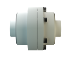
In-Line Detonation Flame Arrester with shut-off valve, for stable detonations and deflagrations in a straight through design, unidirectional
- protects against stabilized burning
- no expensive emergency switch-offs are required
- temperature monitoring is not necessary
- minimum number of FLAMEFILTER® discs
- easy to maintain
- the individual FLAMEFILTER® discs can be quickly removed and installed
- the FLAMEFILTER® discs can be individually replaced
- provides protection from defl agrations and stable detonations
- ideal protective system for vacuum pumps
- cost efficient spare parts
Função e descrição
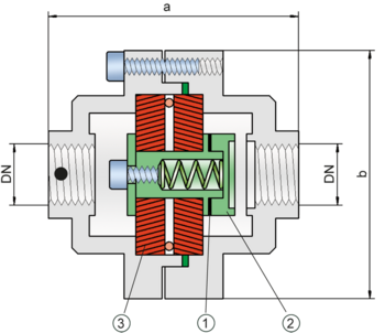
The PROTEGO® DR/SV flame arrester series ideally combines the function of a detonation arrester with the advantages of a shut-off valve. In case of ignition, the fire can be stabilized within the flame arrester when the flammable gas continues to flow. Inside the detonation arrester, is a valve (1) that closes in case of fire, stops the additional supply of fuel and extinguishes the flames. Temperature sensors in combination with an emergency switch off do not have to be installed if the type PROTEGO® DR/SV device is used. This device is particularly useful for the sucction-side protection of compressors and pumps.
The flame arrester protects against deflagrations and stable detonations. It can be installed anywhere in the pipe independently from the distance of the potential ignition source.
Once a detonation enters the flame arrester, energy is absorbed from the detonation shock wave by the central plate disc (2) before the flame is extinguished in the narrow gaps of the two FLAMEFILTER® discs (3). This device can be used for fluids of explosion group IIA (NEC group D).
The in-line detonation flame arresters are unidirectional and equipped with a threaded connection. The thread can be executed to international standards. The standard design can be used up to an operating temperature of +60°C / 140°F and an (absolute) operating pressure up to 1.1 bar / 15,9 psi.
EU conformity according to the currently valid ATEX directive. Approvals according to other national/international regulations on request.
Tabela de dimensões
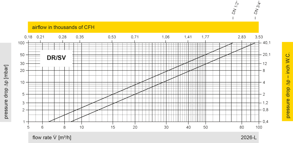
Para selecionar o diâmetro nominal (DN), utilize os diagramas de vazão nas páginas seguintes
| DN | G ½" | G ¾" |
| a | 115 | 115 |
| b | 100 | 100 |
Seleção do material do corpo
| Versão | A | B |
| Corpo | Latão | Aço inoxidável |
| Vedação | WS 3822 | WS 3822 |
| Conjunto abafador de chamas | A | A, B |
Combinações de material do conjunto abafador de chamas
| Design | A | B |
| FLAMEFILTER®* | Stainless Steel | Stainless Steel |
| Spacer | Stainless Steel | Stainless Steel |
| Support for FLAMEFILTER® | Brass | Stainless Steel |
| Washer | Brass | Stainless Steel |
Seleção do grupo de explosão
| MESG | Gr. expl. (IEC / CEN) | Grupo gás (NEC) |
| > 0,90 mm | IIA | D |
Seleção da pressão máx. de trabalho
| DN | G ½" | G ¾" |
| Pmáx. | 1,1 | 1,1 |
Indicação da temperatura máx. de trabalho
| ≤ 60°C / 140°F | Ttemperatura máxima de trabalho admissível em °C |
| - | Designation |
Tipo de conexão
| Rosca para tubo DIN ISO 228-1 | DIN |
Diagrama de vazão

Este diagrama de vazão foi determinado em uma bancada de medição de vazão calibrada e certificada pela TÜV. A vazão V em m³/h se refere ao estado técnico padrão de ar, conforme ISO 6358 (20°C, 1bar). Para conversão em outras densidades e temperaturas, veja o cap. 1: Bases técnicas.


