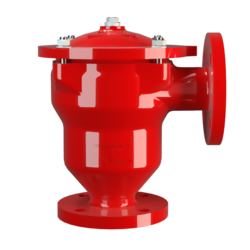
DR/ES-V
In-Line Detonation Flame Arrester with integrated pressure relief valve, for stable detonations and deflagrations in right angle design with shock absorber, unidirectional
- integration of in-line detonation flame arrester and pressure relief valve in one device
- excellent tightness of the valve
- can be used as a detonation-proof valve in suction lines of storage tanks
- optimal use as an overflow valve in venting and gas supply lines
- low number of FLAMEFILTER® discs due to shock absorber technology
- quick removal and installation of the complete PROTEGO® flame arrester unit and the individual FLAMEFILTER® in the casing
- provides protection against deflagration and stable detonation
- advanced design for higher operating temperatures and pressures
- cost-effective spare parts
Función y Descripción
PROTEGO® DR/ES-V series uniquely combines the function of an in-line detonation flame arrester with the function of a pressure relief valve in one device. The device protects against deflagration and stable detonation. The weight-loaded pallet type valve (5) integrated in the shock absorber (1) of the in-line detonation flame arrester is designed as a pressure relief valve. The set pressure of the valve is adjusted in the factory and can range from 2 to 35 mbar (0.8 to 14 inch W.C.). After the pressure increases 40% from its set pressure, the valve completely opens to yield the maximum volumetric flow. If installed in vent headers connected to storage tanks, the valve pallet works as a check valve. This means that the product cannot flow back from the suction line into the tank. Although several functions are integrated in a single housing, the device is extremely easy to service, which is primarily due to the right-angle design.
Once a detonation enters the flame arrester, energy is absorbed from the detonation shock wave by the integrated shock absorber, before the flame is extinguished in the narrow gaps of the FLAMEFILTER® (3). The flame suppression is guaranteed, regardless of the valve pallet position.
The PROTEGO® flame arrester unit (2) consists of several FLAMEFILTER® discs and spacers firmly held in the FLAMEFILTER® casing (4). The gap size and number of FLAMEFILTER® discs depend on the operating conditions of the flowing mixture (explosion group, pressure, temperature). This device is available for explosion groups from IIA to IIB3 (NEC group D to C MESG ≥ 0.65 mm).
The standard design is approved for an operating temperature of up to +60°C / 140°F and absolute operating pressure up to 1.2 bar / 17.4 psi. Devices with special approval for higher pressures and temperatures are available upon request.
EU conformity according to the currently valid ATEX directive. Approvals according to other national/international regulations on request.
Dimensiones
To select the nominal size (DN), please use the flow capacity charts on the following pages
| DN | 25 / 1" | 32 / 1¼“ | 40 / 1½“ | 50 / 2“ | 65 / 2½“ | 80 / 3“ | 100 / 4“ | 125 / 5“ | 150 / 6" | 200 / 8" |
| a | 125 / 4.92 | 125 / 4.92 | 153 / 6.02 | 155 / 6.10 | 198 / 7.80 | 200 / 7.87 | 250 / 9.84 | 332 / 13.07 | 335 / 13.19 | 425 / 16.73 |
| b | 140 / 5.51 | 140 / 5.51 | 183 / 7.20 | 185 / 7.28 | 223 / 8.78 | 225 / 8.86 | 290 / 11.42 | 357 / 14.06 | 360 / 14.17 | 505 / 19.88 |
| c | 237 / 9.33 | 237 / 9.33 | 305 / 12.01 | 305 / 12.01 | 395 / 15.55 | 395 / 15.55 | 460 / 18.11 | 575 / 22.64 | 575 / 22.64 | 863 / 33.98 |
| c1 | 345 / 13.58 | 345 / 13.58 | 410 / 16.14 | 410 / 16.14 | 530 / 20.87 | 530 / 20.87 | 615 / 24.21 | 790 / 31.10 | 790 / 31.10 | 1295 / 50.98 |
| d | 149 / 5.87 | 149 / 5.87 | 210 / 8.27 | 210 / 8.27 | 275 / 10.83 | 275 / 10.83 | 325 / 12.80 | 460 / 18.11 | 460 / 18.11 | 620 / 24.41 |
Selección de materiales para la vivienda
| Design | B | C | D |
| Design | Steel | Stainless Steel | Hastelloy |
| Heating jacket (DR / ES-V-H-...) | Steel | Stainless Steel | Stainless Steel |
| Cover with shock absorber | Steel | Stainless Steel | Hastelloy |
| Gaskets | PTFE | PTFE | PTFE |
| Valve seat | Stainless Steel | Stainless Steel | Stainless Steel |
| Flame arrester unit | A | C, D | E |
Combinación de materiales para la unidad apagallamas
| Design | A | C | D | E |
| FLAMEFILTER® cage | Steel | Stainless Steel | Stainless Steel | Hastelloy |
| FLAMEFILTER®* | Stainless Steel | Stainless Steel | Hastelloy | Hastelloy |
| Spacer | Stainless Steel | Stainless Steel | Hastelloy | Hastelloy |
Selection of valve pallet
| Design | A | B | C |
| Pressure range | I | II | III |
| Set pressure [mbar] | +2.0 up to +3.5 | >+3.5 up to +14 | >+14 up to 35 |
| [inch W.C.] | +0.8 up to +1.4 | >+1.4 up to +5.6 | >+5.6 up to 14 |
| Valve pallet | Aluminium | Stainless Steel | Stainless Steel |
| Sealing | FEP | FEP | Metal to Metal |
Selección del grupo de explosión
| MESG | Expl. Gr. (IEC / CEN) | Gas Group (NEC) |
| > 0,90 mm | IIA | D |
| ≥ 0,65 mm | IIB3 | C |
Selección de la máxima presión de operación
| Expl. Gr. | DN | 25 / 1" | 32 / 1¼" | 40 / 1½" | 50 / 2" | 65 / 2½" | 80 / 3" | 100 / 4" | 125 / 5" | 150 / 6" | 200 / 8" |
| IIA | Pmax | 4,0 / 58.0 | 4,0 / 58.0 | 4,0 / 58.0 | 4,0 / 58.0 | 2,9 / 42.1 | 2,9 / 42.1 | 2,0 / 29.0 | 2,0 / 29.0 | 2,0 / 29.0 | 1,2 / 17.4 |
| IIB3 | Pmax | 3,0 / 43.5 | 3,0 / 43.5 | 2,0 / 29.0 | 2,0 / 29.0 | 2,0 / 29.0 | 2,0 / 29.0 | 1,5 / 21.7 | 1,4 / 20.3 | 1,4 / 20.3 | 1,1 / 15.9 |
Especificación de la máx. temperatura de operación
| ≤ 60°C / 140°F | Tmaximum allowable operating temperature in °C |
| - | Designation |
Tipo de bridas de conexión
| EN 1092-1; Form B1 |
| ASME B16.5 CL 150 R.F. |
Modelo y especificación
There are two different designs available:
Basic version of the detonation arrester with check valve | DR/ES- V - – |
Detonation arrester with check valve and heating jacket | DR/ES- V - H |
Set pressure
| Pressure: | +2.0 mbar | +35 mbar | |
| +0.8 inch W.C. | +14 inch W.C. |
Diagrama de flujo volumétrico


Los diagramas de flujo volumétrico han sido determinados con un banco de pruebas de caudal calibrado y certifi - cado por TÜV. El flujo volumétrico V. en [m³/h] y el CFH se refi eren a las condiciones estándar de referencia de aire según ISO 6358 (20°C, 1bar). La conversión a otras densidades y temperaturas están referidas en el Vol. 1: “Fundamentos Técnicos”.

