BE/HR-400
Deflagration Flame Arrester, endurance burning proof, End-of-Line
Características
Función y descripción
Protection Against Atmospheric Deflagration and Endurance Burning
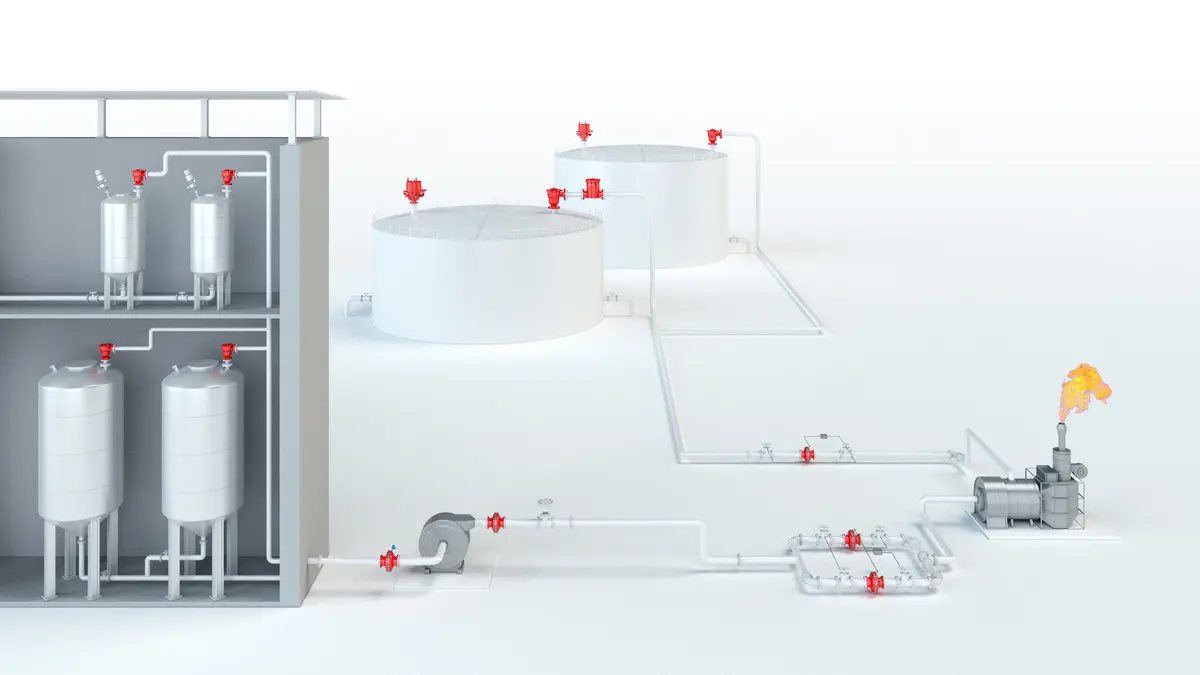
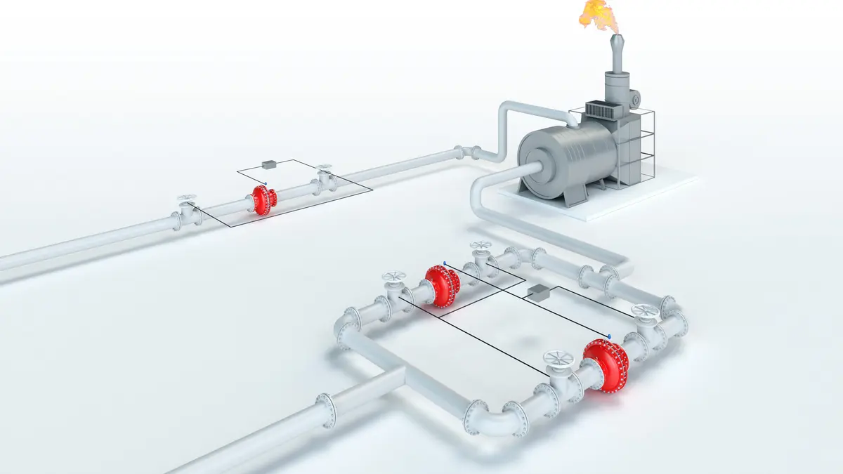
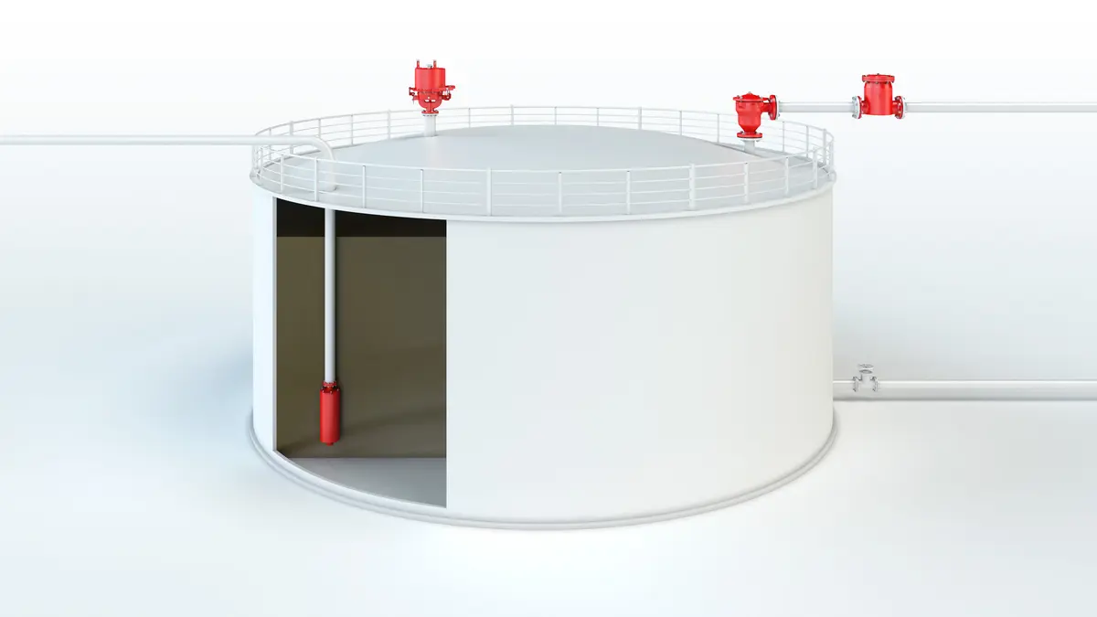
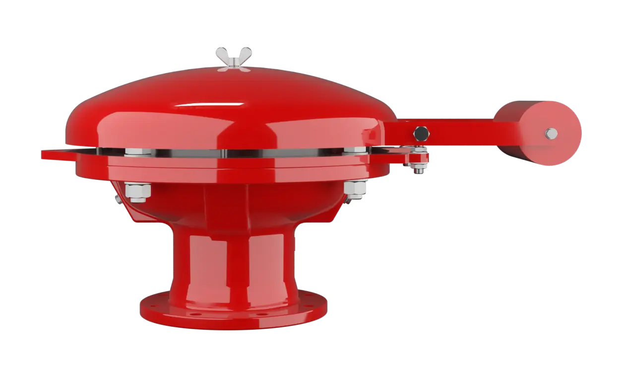
The PROTEGO® BE/HR-400 End-of-Line Deflagration Flame Arrester Deflagration flame arrester Flame arrester designed to prevent the transmission of a deflagration. It can be an end-of-line flame arrester or an in-line flame arrester. is designed to protect large vessels and process engineering apparatus which are not pressurized. The device Device A device is a pipe component that influences the media flow by opening, closing, or partially shutting off the flow channel or by dividing or mixing the media flow. provides protection against flame transmission through atmospheric deflagration Deflagration Explosion propagating at subsonic velocity. and stabilized flames which can burn for very long time on the flame arrester Flame arrester Device fitted to the opening of an enclosure, or to the connecting pipe work of a system of enclosures, and whose intended function is to allow flow but prevent the transmission of a flame. element surface, so called endurance burning Endurance burning Stabilized burning for an unlimited time. . Main application area is on in- and out-breathing and vent lines, with the goal to prevent flame transmission caused by endurance burning or atmospheric deflagration from propagating into the vessel Vessel Container or structural envelope in which materials are processed, treated or stored. or plant.

Main Component – PROTEGO® Flame Arrester Unit
The BE/HR-400 consists of a housing Housing A housing is a solid shell, which surrounds a content, either protecting the content from external influences, or protecting the environment from the content. (1), a weather hood Weather hood A weather hood is a cover to protect the internal components of a device from environmental influences. (2) and the PROTEGO® Flame Arrester Unit PROTEGO® flame arrester unit The PROTEGO® flame arrester unit is the main component of a flame arrester. It prevents flame propagation. (3). During normal operation, the metal weather hood is in a closed position. If a stabilized flame burns on the Flame Arrester Element surface, the fusible link (5), located in a center position, will melt and an external counterweight Counterweight A counterweight is a weight that is used to balance other weights. will move the weather hood into the open position. The PROTEGO® Flame Arrester Unit consists of two FLAMEFILTER® discs (4), which are installed in a FLAMEFILTER® casing FLAMEFILTER® cage The FLAMEFILTER® cage is a housing for a FLAMEFILTER® set. .

For Explosion Group IIA
The FLAMEFILTER® discs are arranged concentrically and are manufactured in a patented process. The FLAMEFILTER® casing has integrated cooling channels to allow heat to be transferred away from the center of the device. The PROTEGO® BE/HR-400 End-of-Line Deflagration Flame Arrester is available for substances from explosion Explosion Abrupt oxidation or decomposition reaction producing an increase in temperature, pressure, or in both simultaneously. group IIA (NEC group D). The standard design can be used for operating temperatures up to +60°C / 140°F. EU conformity according to the currently valid ATEX directive. Approvals according to other national/international regulations on request.
Dimensiones
To select the nominal size Nominal size The nominal size is an alphanumeric designation of size for components in a piping system, used for reference purposes, comprising the letters DN followed by a dimensionless integer that is indirectly related to the physical size of the bore or outside diameter of the connections, expessed in millimeters. (DN), please use the flow capacity charts on the following pages
| DN | 150 / 6" | 200 / 8" |
| NG | 400 / 16" | 400 / 16" |
| a | 600 / 23.62 | 600 / 23.62 |
| b | 545 / 21.46 | 545 / 21.46 |
| c | 485 / 19.09 | 485 / 19.09 |
Dimensiones en mm / pulgadas
Dimensions for deflagration flame arrester with integrated heating coil Heating coil A heating coil is a pipe connection consisting of several pipe sections. upon request
Selección de materiales para la vivienda
| Design | A | B |
| Housing | Steel | Stainless Steel |
| Weather hood | Steel | Stainless Steel |
| Flame arrester unit Flame arrester unit Flame arrester casing with FLAMEFILTER® set. | A, B | B |
Special materials upon request
Combinación de materiales para la unidad apagallamas
| Design | A | B |
| FLAMEFILTER® cage | Steel | Stainless Steel |
| FLAMEFILTER® | Stainless Steel | Stainless Steel |
Special materials upon request
Selección del grupo de explosión
| MESG | Expl. Gr. (IEC / CEN) | Gas Group (NEC) |
| > 0,90 mm | IIA | D |
Special approvals upon request
Tipo de bridas de conexión
| EN 1092-1; Form B1 |
| ASME B16.5 CL 150 R.F. |
other connections upon request
Modelo y especificación
There are two different designs:Special designs available on request
Diagrama de flujo volumétrico
Los diagramas de flujo volumétrico han sido determinados con un banco de pruebas de caudal calibrado y certifi - cado por TÜV. El flujo volumétrico V. en [m³/h] y el CFH se refi eren a las condiciones estándar de referencia de aire según ISO 6358 (20°C, 1bar). La conversión a otras densidades y temperaturas están referidas en el Vol. 1: “Fundamentos Técnicos”.