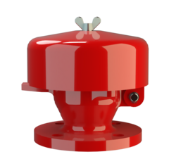
BE/HK-E-IIB
Deflagration Flame Arrester, endurance burning proof, End-of-Line
- endurance burning protection for alcohols and hydrocarbons with MESG ≥ 0,5mm.
- weather hood protects the PROTEGO<® flame arrester unit against environmental impact, such as nesting animals and weather conditions
- in case of fire, the weather hood opens, allowing the flame to be seen from a far distance
- centrally aligned melting element is resistant to chemicals
- modular design enables replacement of individual FLAMEFILTER®discs
- trouble-free maintenance
- provides protection against atmospheric deflagrations and endurance burning
- cost-effective spare parts
Función y Descripción
The PROTEGO® BE/HK-E end-of-line deflagration flame arrester was specifically developed for vessels which are not pressurized and store Ethanol or other alcohols. The combustion of alcohol requires a modified flame arrester element design to provide protection against endurance burning. In addition, the device provides protection against atmospheric deflagration. It is typically installed on in - breathing and out-breathing vent lines to prevent flame transmission into the vessel or plant caused by endurance burning or atmospheric deflagration.The PROTEGO® BE/HK-E consists of the housing (1), a weather hood (2), and the PROTEGO® flame arrester unit (3). During normal operation, the metal weather hood is in a closed position. If a stabilized flame burns on the flame arrester element surface, the melting element (5), located in a center position, will melt, and the spring- loaded weather hood will open. The PROTEGO® flame arrester unit consists of two FLAMEFILTER ® discs (4), which are installed in a FLAMEFILTER® casing. The PROTEGO® BE/HK-E end-of-line deflagration flame arrester is available for alcohols and other substances with MESG ≥ 0,5mm.
The standard design can be used for operating temperatures up to +60°C / 140°F.
EU conformity according to the currently valid ATEX directive. Approvals according to other national/international regulations on request.
Dimensiones
To select the nominal size (DN), please use the flow capacity charts on the following pages
| DN | 20 / ¾" | 25 / 1" | 32 / 1¼" | ||||
| a | 163 / 6.42 | 163 / 6.42 | 163 / 6.42 | ||||
| b | 180 / 7.09 | 177 / 6.97 | 177 / 6.97 |
Selección de materiales para la vivienda
| Design | B | C |
| Housing | Steel | Stainless Steel |
| Weather Hood | Steel | Stainless Steel |
| Flame arrester unit | A | A, B |
Combinación de materiales para la unidad apagallamas
| Design | A | B |
| FLAMEFILTER® cage | Stainless Steel | Stainless Steel |
| FLAMEFILTER® | Stainless Steel | Hastelloy |
| Spacer | Stainless Steel | Hastelloy |
Selección del grupo de explosión
| MESG | Expl. Gr. (IEC / CEN) | Gas Group (NEC) |
| ≥ 0,5 mm | IIB | – |
Tipo de bridas de conexión
| EN 1092-1; Form B1 |
| ASME B16.5 CL 150 R.F. |
Modelo y especificación
There are two different designs:
End-of-line deflagration flame arrester, basic design | BE/HK-E - – |
End-of-line deflagration flame arrester with heating jacket | BE/HK-E - H |
Special designs available on request
Diagrama de flujo volumétrico

Los diagramas de flujo volumétrico han sido determinados con un banco de pruebas de caudal calibrado y certifi - cado por TÜV. El flujo volumétrico V. en [m³/h] y el CFH se refi eren a las condiciones estándar de referencia de aire según ISO 6358 (20°C, 1bar). La conversión a otras densidades y temperaturas están referidas en el Vol. 1: “Fundamentos Técnicos”.

